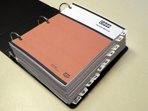
Case W30 Loader Service Manual
8-70330
1,446 Pages
Color and Foldout Diagrams
Table of Contents:
GENERAL
Safety Rules, Service Manual Introduction, and Torque Specifications
Maintenance and Lubrication
General Engine Specifications
Detailed Engine Specifications
ENGINES
Engine Stall Tests, Engine and Radiator Removal and Installation
Muffler, Air Cleaner, Ether Injection System, and Turbocharger
Engine Tune-Up
Cylinder Head, Valve Train, and Camshaft
Cylinder Block, Sleeves, Pistons, and Rods
Crankshaft, Main Bearings, Flywheel, and Oil Seals
Lubrication System
Cooling System
Engine Troubleshooting
Reconditioning Engine Block
Turbocharger Failure Analysis
FUEL SYSTEM
Fuel Tank, Fuel Lines, and Engine Controls
Fuel System and Filters
Robert Bosch Fuel Injection Pump
17 mm Fuel Injectors
ELECTRICAL
Removal and Installation of Electrical Components
Electrical System Specifications and Troubleshooting
Electrical Schematics
Instrument Cluster and Optional Gauges
Batteries
Alternator - 40 Ampere Delco-Remy
Alternator - 65 Ampere Delco-Remy
Alternator - Bosch
Starter - Delco-Remy 1114872
Starter - Delco-Remy 1193797
STEERING
Steering System Troubleshooting and Pressure Checks
Removal and Installation of Steering System Components
Steering Control Valve
Steering Cushion Valve, Flow Control Valve
Center Pivot
Auxiliary Steering Pump and Check Valve
Steering Cylinder
POWER TRAIN
Transmission Maintenance
Allison and Twin Disc Transmission Troubleshooting and
Pressure Checks
Allison and Twin Disc Transmission Operation
Transmission Removal and Installation
Allison and Twin Disc Transmission Disassembly and Assembly
ZF Transmission Disassembly and Assembly
Hydraulic Troubleshooting for ZF Transmissions
Transmission Controls
Drive Shafts and Trunnion
Axles and Differentials
Wheels and Tires
BRAKES
Air System Operation and Diagram
Removal and Installation of Brake System Components
Air Compressor, Governor, Reservoir, and Safety Valve
Brake Valve, Double Check Valve, and Stoplamp Switch
Brake Actuator
Pressure Reducing Valve and Pressure Protection Valve
Air Horn and Air Horn Valve
Alcohol Evaporator
Disc Brakes
Parking Brake Actuator and Parking Brake Valve
HYDRAULICS
Hydraulic System Specifications, Diagrams, Maintenance, Troubleshooting, and Pressure Checks
Cleaning the Hydraulic System
Removal and Installation of Hydraulic System Components
Loader and Steering Pump
Loader Control Valve
Unloading Valve
Remote Control Valves, Pressure Reducing Valve, and Accumulator
Remote Control Valves
Cylinders
CHASSIS/MOUNTED EQUIPMENT
Air Conditioning Troubleshooting
Air Conditioning System
Loader
Cab and Canopy
Operators Seat and Seat Belts
Decals, Painting, and Noise Control
Electrical Schematics
Rear Chassis, Machines with Allison or Twin Disc Transmission
Front Chassis, Machines with Allison or Twin Disc Transmission
Rear Chassis, Machines with ZF Transmission
Front Chassis, Machines with ZF Transmission
Cab
Air System Diagram
Hydraulic System Schematic |


